
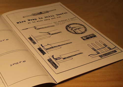
We strongly recommend reading through the “Wire Wrap is Still Useful” comic before beginning.
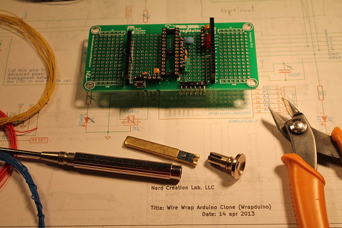
After that open your kit and insure you have all the parts:
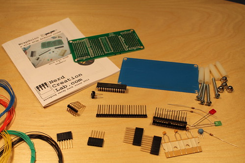
1ea Quick start guide & schematic
1ea PCB
1ea 28pin DIP socket
1ea 22pin SIP socket
2ea 6pin female header
2ea 8pin female header
1ea 6pin male header (straight – optional to bend at install)
1ea push button
1ea Atmega328 (pre-programmed with Arduino boot-loader)
1ea green LED
1ea red LED
2ea 470ohm resistors
1ea 10k ohm resistor
1ea 16mhz resonator
3ea 0.1uF capacitors
3ft black wire
3ft red wire
3ft green wire
3ft blue wire
3ft yellow wire
1ea acrylic base plate
4ea screws
4ea spacers
4ea cap nuts
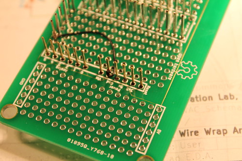
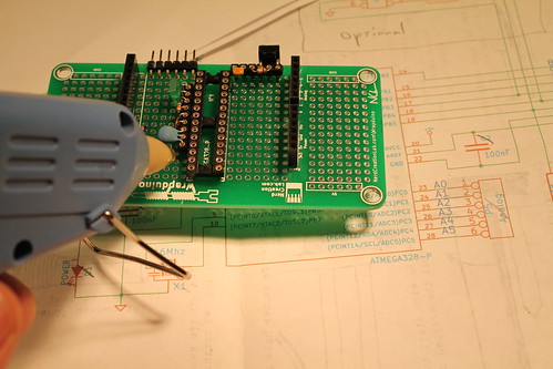
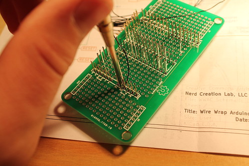
Now begin placing the components. It is best to start by placing the female headers and the DIP socket.

One note is that if you want to use the +5v and Gnd rails in the proto space on the “wings” then at this stage you should solder the +5v and gnd pins on the female header (NOTE: this picture will be updated to not show the wires, just the solder)
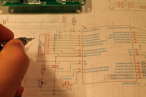
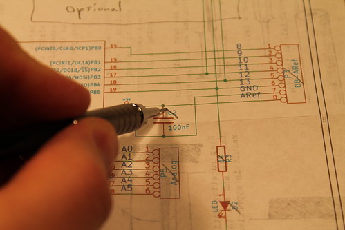
As you add components it is a good idea to check them off on your schematic so that you keep track of your progress.
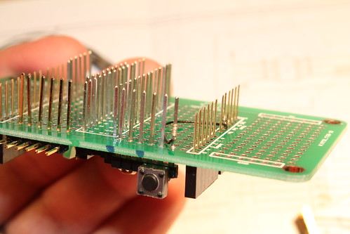
You should then add the FTDI header (6pin male header). We recommend you bend the longer pins over 90° so the connector is flush with the board but you can leave them vertical if you want.
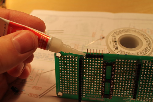
Most of the components you have added will be loose. You can glue them in with super glue or hot glue. Or if you would rather you can tack solder a few of the pins to the perf board. But it is nice to do it with out any solder.
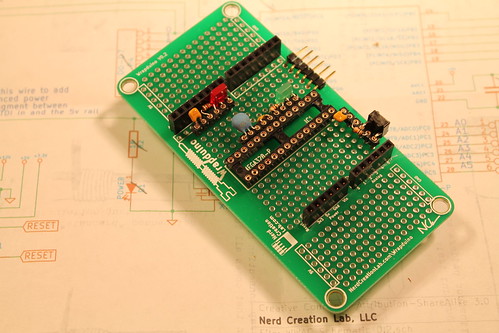
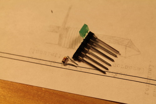
The next step is to decide where the rest of the components are going to go. We recommend the following arrangement as it optimizes the wire runs and leaves space for additional components.
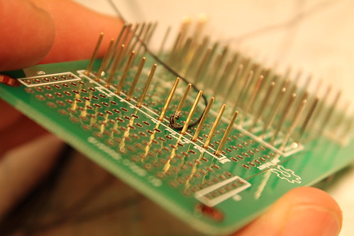
Start by bending and clipping the leads to the length shown.
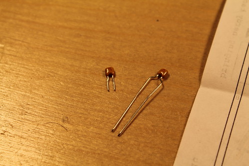
The leads should go all the way into the sockets. Don’t cut them too short to start with as you can always trim more later.
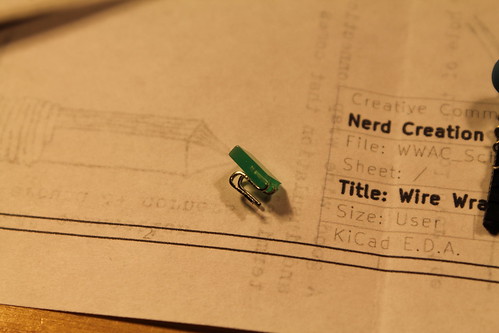
For the LEDs you can bend the leads into a ‘S’ shape and the LED can sit beside the socket. (Add another picture here showing the LED orientation)
As you continue adding components be sure to check them off on your schematic.
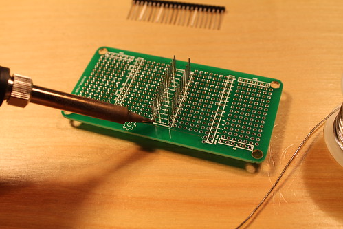
Once again, if you want to hold the sockets to the board as you go you can glue or tack solder them. This is optional as once you start wrapping the wires will hold them in place.
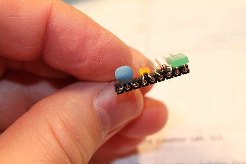
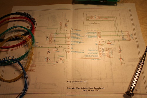
Now that all the components and sockets are placed gather you wire, wire cutters, and wire wrap tool. Then you should start deciding what color wire you want to use where.
The recommended coloring scheme is to use black for all your ground wires and red for the +5v wires. Then use a combination of the blue, yellow, and green for the rest. You can go over your schematic and mark what color each wire will be. The image below shows alternating blue, green, yellow, blue, green, yellow, etc… for all the remaining pins. You could also make all the analog pins one color, D0-D7 another, and D8-Aref the third.
Now we are ready to start wrapping! Once again be sure you are familiar with “Wire Wrap is Still Useful.”
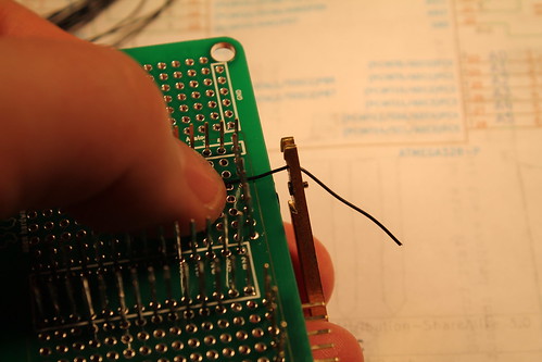
Take your wire and strip approx. 3/4″ of insulation from one end. (There should be a simple stripper on or in your wire wrap tool).
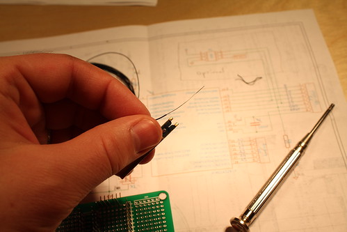
Now insert the stripped wire into the small outer hole in end of the wire wrap tool.

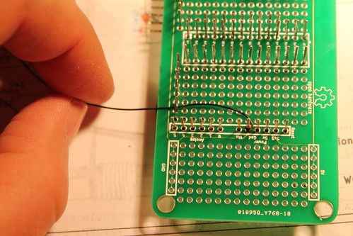
Then slip the tool over the terminal.
Then slowly turn the tool until the wire is completely wrapped. (The wire broke during this connection so it only has 4 wraps, you should aim for 6-12 so it would be best to remove this wrap and start again.)
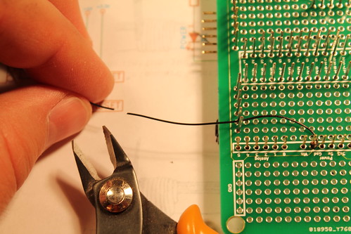
Now route the wire around any other pins and leave some extra slack.
Then cut (leaving enough length for the wrap).
strip
and wrap the other end. (This wrap is better, with approx. 10 wraps. It could be a little lower on the pin, but it should be fine.)
Continue this process for each connection. Check them off on your schematic as you go so that you do not forget any of them.
Additional photos of progress and complete assembly to be added.
Also pictures of base plate installation to be added.