Cartridge Theory
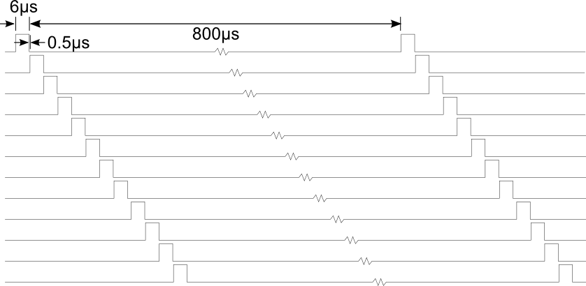
There is no published information about driving the HP C6602, however it is similar to the HP 51604 and the spec sheets say the C6602 can print faster than the 51604. According to “Inkjet Applications” by Matt Gilliland the HP 51604 should be driven with a 6μs 21V pulse with a 0.5μs delay before firing a different nozzle and an 800μs delay between two pulses on a given nozzle. This was used as a starting point for driving the HP C6602.

The digitalOUT() command is too slow but direct port manipulation works.
This code gives 5μs ON & 800μs OFF:
PORTB = PORTB & 01111111;
delayMicroseconds(5);
PORTB |= 10000000;
delayMicroseconds(800);
I have tested the C6602 cartridge to find the extremes of function.
The first test involved holding the voltage at 19V and varying the pulse width from 5μs down until ink stopped spraying and then up until a nozzle failed. It was found that the minimum pulse width that would cause ink to spray was 3μs and the maximum before failure was 20μs. The size of the drops was also examined for each of these pulses and there were no noticeable changes from 3μs – 25μs.
The second test involved holding the pulse width at 5μs and varying the voltage from 19V down until ink stopped spraying and then up until a nozzle failed. It was found that the minimum voltage that would cause ink to spray was 17.5V and the maximum before failure was 27V. The size of the drops was also examined for each of these voltages and there were no noticeable changes from 17.5V – 27V.
Therefore the C6602 has very much the same requirements as the 51604. The driver circuit should provide a 5-6μs 20-21V pulse with a 0.5μs delay before firing a different nozzle and an 800μs delay between two pulses on a given nozzle.
Circuit theory
All of that says an Arduino can generate the pulses but we have two problems.
- The cartridge needs 20-21V.
- There are 12 nozzles and we would like to not use 12 output pins (the Arduino only has 18 free to start with).
Power
It is not easy to find a 20-21V power supply which leaves two options. The first option is to use a higher voltage supply (i.e 24V) and regulate it down with a LM317 3-Terminal Adjustable Regulator. I did this for some of the very early tests. The disadvantage of this is that 24V is too high for most of the other electronics which then requires a second 12V or less supply for the logic.
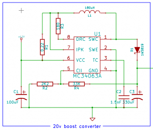
The second option is to use a MC34063 Step-Up/Down/Inverting Switching Regulator. This allows using a 9-12V supply which can also power the logic, as most microcontroller boards can take 12V in. This requires some additional components such as an inductor, diode, several capacitors, and resistors. The datasheet was used to calculate the required resistor pair to generate 20V.

Pin count
To reduce the pin count there are two main options I considered. The first is a shift register and the second is a demultiplexer. The shift register can output on all of its pins at once but requires stepping the data into it. The demultiplexer can only output to a single pin at a time but the pin can quickly be selected by a four bit address. Since the specifications of the head do not allow firing all the nozzles at the same time the demultiplexer is a better choice. It is less processor intensive to select the output pin with a four bit address than with shifting the data out.
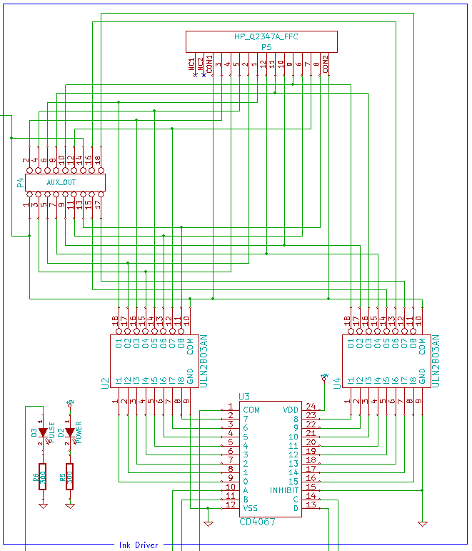
The CD4067 demultiplexer was selected because it would support the positive logic needed to drive the ULN2803 Darlington arrays. If a 74HC154 was used it would have required additional hex inverters as the outputs are all normally high and a single line is pulled low at time.

The following picture shows what the A, B, C, D, and Pulse lines look like during a single firing of each nozzle 1-12.

As you can see the A, B, C, & D lines select the nozzle with binary and then the pulse travels through the CD4067 “COM” input and out the selected channel to the Darlington arrays. One additional thing to note is that the CD4067 supports 16 channels and these 4 extra outputs are available on the AUX_OUT header for other future uses.
